Figure 37. The PBC Symmetry Panel
This panel shows settings for a 3D periodic system constrained to the indicated space group.
The Edit=>PBC menu path and the Crystal Editor button both bring up the PBC window. This tool is used to specify unit cells for periodic systems. In order to use this feature, as well as to perform Periodic Boundary Conditions calculations in Gaussian, you will need some understanding of periodic systems, space groups, and general related terminology. This background is assumed in this section.
The PBC window contains five panels:
Symmetry: Specifies the dimensionality of the unit cell, the lattice system and space group constraints.
Cell: Specifies the dimensions of the unit cell and also contains controls for repositioning and and reducing cell contents.
View: Specifies how many cells are displayed in each direction in the view window, as well as controlling the display/non-display of various items.
Contents: Contains a list of atoms in the cell as an embedded mini Atom List Editor. Its Bonds popup also allows you to modify bonding.
Reduce: Allows you to reduce the dimensionality of a unit cell (e.g., from a 3D system to a surface).
From the highest-level view, a typical process of building a periodic system might proceed as follows (consult the PBC tutorials in the GaussView online help for more detailed instructions):
[1] Use the Symmetry panel to specify the number of dimensions and desired space group.
[2] Add atoms to the cell using the mouse or via the Contents panel.
[3] Remove any unwanted atoms (e.g., if you used a group fragment as a shortcut to creating the necessary atoms).
[4] Set the unit cell size using the Cell panel.
[5] Adjust bonding using the Contents panel if appropriate.
The controls in each of the PBC window panels will be described in the following subsections.
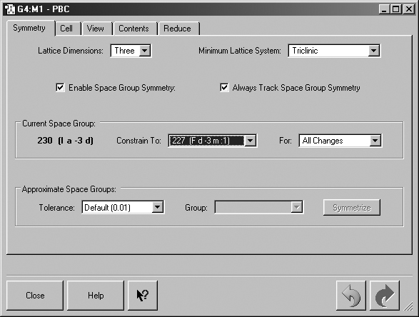
The Symmetry panel is displayed in Figure 37.
Figure 37. The PBC Symmetry Panel
This panel shows settings for a 3D periodic system constrained to the indicated
space group.
Lattice Dimensions: Sets the number of dimensions in which the system has translational symmetry (i.e., is periodic): One for polymers, where a is the translation vector; Two for sheets, where a and b are the translation vectors, and Three for crystals, where a, b and c are the translation vectors.
Note that the dimensionality of a lattice is not necessarily the same as the dimensionality of the corresponding cell contents. For example, the monomers of a polymer (a one-dimensional lattice) are generally not linear.
Minimum Lattice System: Constrain 3D cell changes to preserve at least the specified lattice system. For example, if Cubic is selected, then all cell angles will be constrained to be 90 degrees, and the cell will be constrained to being a cube. Note that space group constraints override lattice system constraints.
Enable Space Group Symmetry: Monitor space group symmetry and enforce space group symmetry constraints.
Always Track Space Group Symmetry: Monitor space group symmetry during interactive changes to cell contents (e.g., continuously as the bond length slider is used) instead of only computing it after the change is completed.
These controls appear in the Current Space Group area of the panel
Constrain To: Constrain changes to preserve at least the specified space group. All space groups to which the system exactly belongs are available for constraint.
For: Enforce space group symmetry constraints for at least the specified type(s) of changes. Cell Changes refers to changes in the cell lengths or angles. Contents Changes refers to changes in the numbers, types and/or positions of atoms and bonds. The default is All Changes.
These controls appear in the Approximate Space Group area of the panel
Tolerance: Set the tolerance for approximately belonging to a space group, in fractional coordinates. A selection can be made from the list or you can enter any value you want into this field. Valid input consists of any floating point number (e.g., 0.25) or fraction (e.g., 1/4).
Group: Set the space group to exactly symmetrize to when the Symmetrize button is pushed. All applicable space groups within the specified tolerance are listed.
The Symmetrize button will symmetrize the system to exactly belong to the specified Group.
The Cell panel is displayed in Figure 38.

Figure 38. The PBC Cell Panel
This panel is being used to resize the unit cell. The values in the disabled
fields are predetermined by the space group to which the structure is constrained
(see Figure 37).
The Cell Changes popup specifies what should happen to the cell contents when the cell parameters are changed. When Fix Contents' Cartesian Coordinates is selected, the contents of the cell and their Cartesian coordinates after a change are the same as before the change, provided the atoms are still within the cell boundaries.
The setting of the Add/Remove Atoms checkbox affects the operation of this choice:
If unchecked, the contents of the cell and their Cartesian coordinates after a change are the same as before the change. For example, if there is one atom in the cell with fractional coordinates (1/2, 1/2, 1/2), and the length of a is doubled, the contents of the cell after the change will still be one atom, but with fractional coordinates (1/4, 1/2, 1/2).
If checked, the contents of the cell after a change is defined as whatever atoms are within the cell boundaries after the change. For example, if there is one atom in the cell with fractional coordinates (1/2, 1/2, 1/2) and the length of a is doubled, the contents of the cell after the change will be two atoms, with fractional coordinates (1/4, 1/2, 1/2) and (3/4, 1/2, 1/2).
When Cell Changes is set to Fix Contents' Fractional Coordinates, the contents of the cell and their fractional coordinates after a change are the same as before the change. For example, if there is one atom in the cell with fractional coordinates (1/2, 1/2,1/2) and the length of a is then doubled, the contents of the cell will still be one atom with fractional coordinates (1/2, 1/2, 1/2). This option is often the more useful of the two.
The controls in the Cell Lengths and Cell Angles areas control the geometry of the cell:
a, b, c: Set the length (in Angstroms) of the indicated cell vector.
Scale by: Scale the length of the a cell vector by a positive number.
Alpha, Beta, Gamma: Set the angle (in degrees) between the other cell axes (i.e., between the b and c cell axes for the Alpha field). The specified angle is changed by rotating one or both of the other two cell axes, as specified in the corresponding Rotate field. Even for non-orthogonal cells, the rotation(s) used to change an angle are constrained to not change the other two angles.
Padlock icon: If locked, freeze the specified angle at its current value. The angle is also constrained to its current value during vertex placement.
Rotate: Specify the axes to rotate when the specified angle is changed. You have the choice of selecting either one or both of the other two axes.
The fields in the next two rows of the panel control placement of the cell vertices (which define the boundaries of the unit cell)
Place: Enable/disable cell vertex placement.
Vertex: Specify the cell vertex to be placed.
Moving: Specify whether to move the vertex only or move the whole cell.
Using: Specify whether to place the vertex using mouse selection in the view window or fractional coordinates.
When Using is set to Mouse, the Location popup specifies the location type for vertex placement using mouse selection in the view window: Atom means that the vertex will placed on the atom you click on, Between Two Atoms means that the vertex will be placed midway between the two atoms you click with the mouse, and Any Point means that the vertex will be placed at the point in space where you click.
When Using is set to Coordinates, additional fields appear for the desired fractional coordinates. Click the Apply button to place the vertex at the specified coordinates.
The five buttons at the bottom of the panel have the following purposes (the examples use a 3D cell)
Trim Contents: Change the cell contents using the specified method. If Delete All Atoms Outside Cell is selected, then all atoms outside the cell boundary are deleted. If Translate All Atoms Inside Cell is selected, then all atoms outside the cell boundary are translated to the equivalent position inside the cell boundary. Redundant atoms are deleted.
An atom is outside the cell boundary if one or more of its fractional coordinates is less than zero or greater than or equal to one.
Resize to Fit Contents: Change the cell lengths to fit the cell contents, then center the contents. A 0.5 Angstrom cushion is added to each side of the cell.
Center Contents: Translate the cell so that its center (1/2, 1/2, 1/2) coincides with the contents' center of nuclear charge.
Align Axes: Align the Cartesian origin and axes with those of the cell. The cell origin (0,0,0) is first translated to Cartesian origin. The cell is then orthogonally rotated so that the c cell axis is aligned with the Cartesian Z-axis. The cell is then orthogonally rotated so that the b cell axis is aligned with the Cartesian Y-axis. The cell is then orthogonally rotated so that the a cell axis is aligned with the Cartesian X-axis.
Switch Axes: Switch the specified pair of cell axes. For example, if a <-> b is selected, then the a vector becomes the b vector and vice-versa.
The View panel is displayed in Figure 39.
a, b, c, -a, -b, -c: Set the number of cells to display along the specified axis (in the positive or negative direction, as indicated). This number is for display purposes only; it does not change the contents of the unit cell unless the Combine button is pushed. See Figure 40.
Combine: Combine all of the displayed cells into one larger "supercell."
Show Reference Cell Edges: Display cell edges and vertices of the reference cell.
Show Replicate Cell Edges: Display cell edges and vertices of all replicate cells.
Show All Boundary Atoms: Display all atoms on cell boundaries.
View Along: Align the specified Cartesian or cell axis of the system with the axis perpendicular to the plane of the computer monitor.

Figure 39. The PBC View Panel
This panel specifies how many unit cells appear in the view window.
Replicate Contents Display: Specify how the atoms and bonds in replicate cells should be displayed. The choices include a normal display, a dulled-out normal display, the display format defined for one of the ONIOM layers in the Display Format preferences Molecule panel, or no display.


Figure 40. Displaying Multiple Unit Cells
These two view windows show a 3D gallium arsenide structure. In the left
window, one unit cell is shown (including all boundary atoms). In the right
window, two cells in each direction are displayed. The contents of replicate
cells are displayed using the Low layer display format (their default display
mode).
General Positions: List of equivalent positions (in fractional coordinates) for the current (constraint) space group. The Display popup specifies how to view the asymmetric units corresponding to the general positions for the current (constraint) space group.
Special Positions: List of special positions (in fractional coordinates) for the current (constraint) space group. The Display po
.pup specifies how to view the special positions for the current (constraint) space group.
The Contents panel contains an embedded mini Atom List Editor which functions like the corresponding tool. It is illustrated in Figure 41.
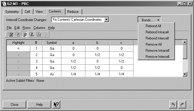
Figure 41. The PBC Contents Panel
This panel displays an atom list for the contents of the unit cell. It also
contains the Bonds button which allows you to rebond atoms as appropriate.
The controls at the top of the panel are
Intercell Coordinate Changes: Specify how to handle intercell coordinate changes. The selections are Fix Contents' Cartesian Coordinates, Fix Contents' Fractional Coordinates, and Fix Cell Parameters.
Bonds: Recalculate or remove intracell and/or intercell bonds. Rebonding is based on distance criteria. The various selections on this menu are shown in Figure 41.
The Reduce panel is displayed in Figure 42.
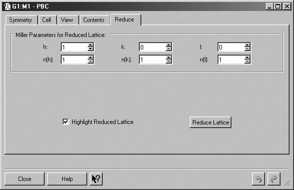
Figure 42. The PBC Reduce Panel
This panel is used to convert a unit cell to one having a lower dimensionality.
h, k, l: Set the Miller index for the reduced lattice intercept along the a, b or c axis (respectively).
n(h), n(k), n(l): Set the multiple for the reduced lattice intercept along the a, b or c axis.
Highlight Reduced Lattice: Indicate the pending reduced lattice in the view window (see Figure 43).
Reduce Lattice: Reduce the lattice by one dimension according to the specified Miller parameters.
Figure 43 illustrate the reduction process by reducing a palladium 3D cell to a surface two atoms deep. In the left illustration, we see the highlighted view window resulting from the settings in the Reduce panel from Figure 42. The light colored plane indicates the cut.
The right illustration in Figure 43 displays the resulting cell. We have highlighted atoms which are below the plane of the page in the window in order to indicate depth. We have also realigned the view to look along the X axis using the PBC View panel's View Along popup.


Figure 43. Reducing a 3D Pd Cell to Pd(100)
Here we create a Pd(100) surface from a Pd crystal.